Cube ATX Power Supply
Background:
The original next cube power supply requires a minimum load usually
supplied by the megapixel display in order to function. Using a
soundbox with a VGA monitor does not provide this load. This leaves 2
options. Create a load to simulate the display being attached or adapt
an ATX power supply. I chose the latter.
Next Power Supply Connector:
The next power supply attaches to the backplane using an ERNI 96 pin connector.
Figure 1: ERNI 96 Connector
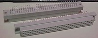
Luckily these are still readily available. The pinout is as follows:
Figure 2: Front Facing View of the Next Power Supply Connector
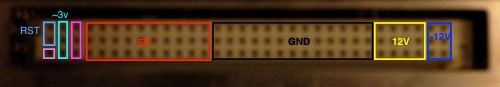
Each column except column 32 (Left most column), is shorted together.
Pin 96 starts with the reset. Column 31 is the input from the logic
board. When the power button is pressed, a voltage of about 3V is
delivered from the main board battery. This is important, because it
will be needed for 'soft booting' the system. The -12V rails are in the
first 2 column positions and will be neglected for this modification.
They are used solely for the next monitor.
The adapter board:
The basic adapter board is very simple to construct. Simply connect 5V,
12V, and GND(COM) to the appropriate columns on the ERNI 96 pin
connector.
Figure 3: ATX Connector
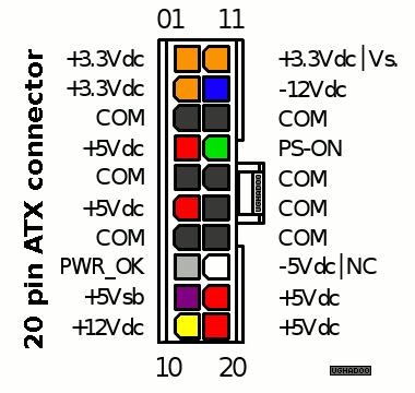
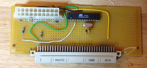
Figure 4: Example Adapter Board
At this point it is possible to short positions 4 (PS-ON) and 5
(COM/GND) on the ATX connector while simultaniously hitting the
keyboard power button to start the system. If the wiring is done
correctly, the system should come alive.
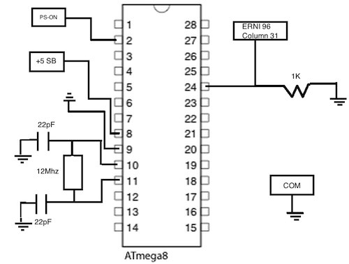
Soft Power:
In order to use the power button on the keyboard to start and stop the
cube there needs to be additional circuitry. As stated previously, when
pressing the power button on the keyboard, ~3V is applied to column 32
on the power supply. Taking this 3V input, it is then necessary to
connect the PS-ON ATX signal to ground. One of the easiest
ways to solve this problem is through the use of a microcontroller
(uC). In this case, an ATMega8 with arduino firmware. Any uC with at
least 1 analog input and 1 digital output will do. Connect column 32 on
the ERNI connector to the analog pin on the uC in series with a
pulldown resistor to GND. Then connect the digital output to the PS-ON
signal of the ATX connector. Keep the digital output high until a
voltage is detected on the analog pin, and then set the PS-ON signal
low to start the system. The uC must continually monitor the 3V signal
so that the system will turn off when appropriate. Fortunately the ATX
specification allows for +5V even when the rest of the supply is off.
Use the +5 SB pin to power the uC.
The following arduino code will monitor the 3V line and power up/down the system:
/*
Next Power ATX Power Adapter
*/
int PowerOn = 2; //The power on pin for ATX
int PowerButton = A1; //Power button from Next
int PowerStatus = 0; //Analog Reading of Power Value
void setup() {
pinMode(PowerOn, OUTPUT);
}
void loop()
{
PowerStatus = analogRead(PowerButton);
if (PowerStatus > 550)
digitalWrite(PowerOn, LOW);
else
digitalWrite(PowerOn, HIGH);
}
Figure 5: Example ATMega8 Configuration
Mounting the finished product:
To mount the finished product, one option is to replace the board in
the existing power supply. There should also be plenty of room for a 1U
ATX supply. The supply used in this mod was taken from a small form
factor PC, so there is plenty of room left over.
Figure 6: ATX PSU Inside the Existing Enclosure
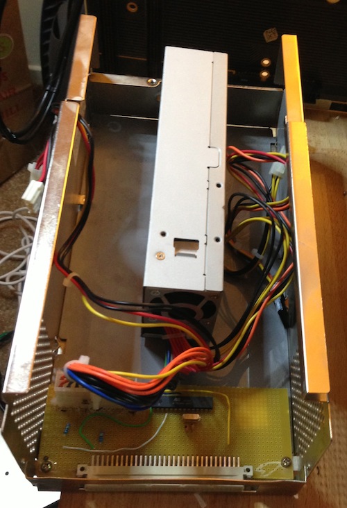
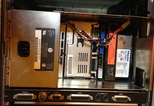
Figure 7: Assembled and Back Inside the Cube Enclosure
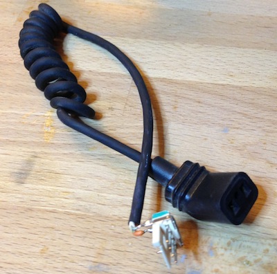
Fan Connector:
The Cube fan runs from a 12V line. If an existing power supply was
used, simply remove the existing fan connector. This ATX PSU had a
floppy style power connector which was used to supply the 12V power.
Figure 8: Fan Connector
Conclusion:
Besides the new style molex connectors, the new PSU is
indistinguishable from the original Next. Everything works as expected
with the soft power implementation as well. Special thanks to the
forum users at http://www.nextcomputers.org, and Rob from
http://www.blackholeinc.com/. Their input has been welcome. I am
giving this information freely, but please do not attempt this mod
unless you are very comfortable with the material. It is very possible
to destroy your equipment!!